【瑞萨RA4系列开发板体验】CANOPEN协议移植及测试
作者:我爱下载
Canopen协议移植和设备通讯测试
Canopen设备通讯测试是基于RA4M2产品CAN总线外设功能的一个小项目应用,其主要功能是通过RA4M2评估板采集开关量状态,通过canopen协议将开关量状态实时发送到canopen主机端。
Can网络构成
根据设计目的,通过RA4M2评估板外扩CAN总线接口,和外部两个CAN总线设备构成一个CAN的局域网,其中一个设备用于canopen 主机,一个设备作为CAN总线的监视设备。
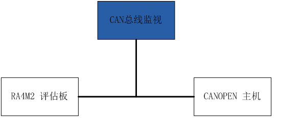
其中: RA4M2为canopen设备,基于canopenNode协议栈 CANOPEN主机采用自制的SLCAN设备,支持python CAN总线监视设备为自制的CAN总线设备。
软件实现
RA4M2评估板canopen协议栈
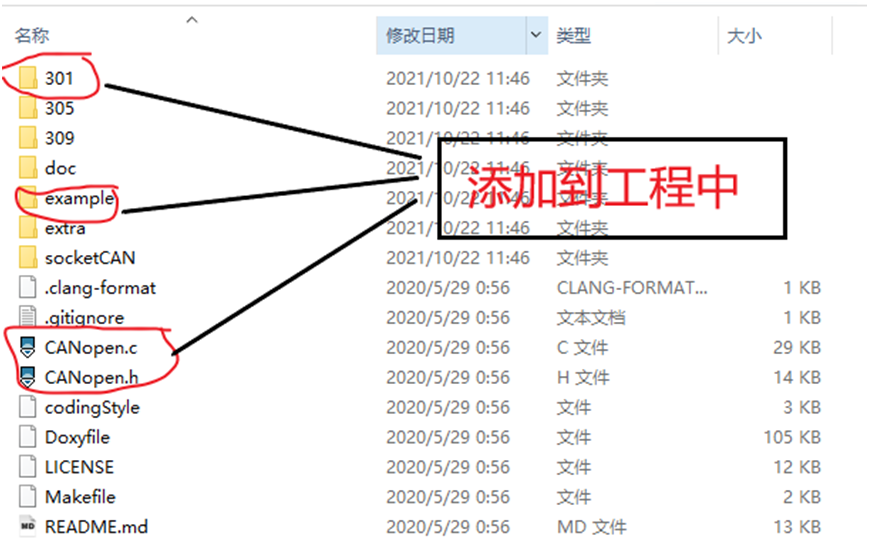
1)canopennode协议栈下载 CanopenNode为github上的一个开源项目,在gitee上面也可以找到,大家搜索即可,这里不展开介绍。 2)canopeneds管理关键 基于开源软件自己编译的,和canopenNode配套的软件,可以直接生成对象字典的C文件和H文件,集成进软件中及可以了。 3)canopenNode的移植 将前面下载的canopenNode源码打开,如下图所示,我们在工程文件下,建立canopen虚拟文件夹,并将301目录,example目录下复制到工程中,再将CANopen.c和CANopen.h复制到工程中,将example目录名修改为port。
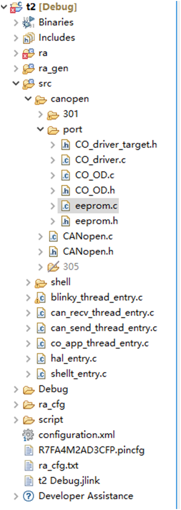
文件添加完成后的工程如下图所示:
移植过程主要时port目录下面CO_driver.c中相关接口函数的移植: - 添加必要的头文件
- CO_CANModule_Init函数移植
- * * * * CO_ReturnError_t CO_CANmodule_init (CO_CANmodule_t
- *CANmodule,
- void *CANptr,
- CO_CANrx_t rxArray[],
- uint16_t rxSize,
- CO_CANtx_t txArray[],
- uint16_t txSize,
- uint16_t CANbitRate)
- {
- FSP_PARAMETER_NOT_USED (CANbitRate);
- … … 此处省略若干代码
- /* configure CAN interrupt registers */
- fsp_err_t err = *FSP_SUCCESS* ;
- /* Open the transfer instance with initial configuration. */
- err = R_CAN_Open (&g_can0_ctrl, &g_can0_cfg);
- assert(*FSP_SUCCESS* == err);
- return CO_ERROR_NO ;
- }
- CO_CANmodule_disable 函数移植
- void CO_CANmodule_disable (CO_CANmodule_t *CANmodule)
- {
- FSP_PARAMETER_NOT_USED (CANmodule);
- /* turn off the module */
- fsp_err_t err = *FSP_SUCCESS* ;
- /* Open the transfer instance with initial configuration.
- */
- err = R_CAN_Close (&g_can0_ctrl);
- assert(*FSP_SUCCESS* == err);
- }
- * CO_CANtx_t CO_CANtxBufferInit (CO_CANmodule_t
- *CANmodule,
- uint16_t index,
- uint16_t ident,
- bool_t rtr,
- uint8_t noOfBytes,
- bool_t syncFlag)
- {
- CO_CANtx_t *buffer = NULL;
- if ((CANmodule != NULL) && (index < CANmodule->txSize)){
- /* get specific buffer */
- buffer = &CANmodule->txArray[index];
- /* CAN identifier, DLC and rtr, bit aligned with CAN module transmit buffer.
- buffer->ident = ((uint32_t)(ident & 0x07FFU) | (uint32_t)(rtr ? 0x8000U : 0U));
- buffer->DLC = (uint32_t)noOfBytes & 0xFU;
- buffer->bufferFull = false;
- buffer->syncFlag = syncFlag;
- return buffer;
- }
- }
l CO_CANinterrupt 函数移植 将原 CO_CANinterrupt 函数调整为CO_CANinterrupt_TX 和CO_CANinterrupt_Rx 两个函数
- void CO_CANinterrupt_Rx (CO_CANmodule_t *CANmodule , _CANMsg_t *rcvMsg)
- {
- /* receive interrupt */
- uint16_t index; /* index of received message */
- uint32_t rcvMsgIdent; /* identifier of the received message */
- CO_CANrx_t *buffer = NULL; /* receive message buffer from CO_CANmodule_t object. */
- bool_t msgMatched = false;
- // rcvMsg = 0; /* get message from module here */
- rcvMsgIdent = rcvMsg->ident;
- {
- /* CAN module filters are not used, message with any standard 11-bit identifier */
- /* has been received. Search rxArray form CANmodule for the same CAN-ID. */
- buffer = &CANmodule->rxArray[0];
- for (index = CANmodule->rxSize; index > 0U; index--){
- if (((rcvMsgIdent ^ buffer->ident) & buffer->mask) == 0U){
- msgMatched = true;
- break ;
- }
- buffer++;
- }
- }
- /* Call specific function, which will process the message*/
- if (msgMatched && (buffer != NULL) && (buffer->CANrx_callback != NULL)){
- buffer->CANrx_callback(buffer->object, ( void *) rcvMsg);
- }
- /* Clear interrupt flag */
- }
- //Interrupt from Transeiver
- void CO_CANinterrupt_Tx (CO_CANmodule_t *CANmodule) {
- /* Clear interrupt flag */
- /* First CAN message (bootup) was sent successfully */
- CANmodule->firstCANtxMessage = false;
- /* clear flag from previous message */
- CANmodule->bufferInhibitFlag = false;
- /* Are there any new messages waiting to be send */
- if (CANmodule->CANtxCount > 0U){
- uint16_t i; /* index of transmitting message */
- /* first buffer */
- CO_CANtx_t *buffer = &CANmodule->txArray[0];
- /* search through whole array of pointers to transmit message buffers. */
- for (i = CANmodule->txSize; i > 0U; i--){
- /* if message buffer is full, send it. */
- if (buffer->bufferFull){
- buffer->bufferFull = false;
- CANmodule->CANtxCount--;
- /* Copy message to CAN buffer */
- CANmodule->bufferInhibitFlag = buffer->syncFlag;
- /* canSend... */
- _can_send(buffer);
- break ; /* exit for loop */
- }
- buffer++;
- }/* end of for loop */
- /* Clear counter if no more messages */
- if (i == 0U){
- CANmodule->CANtxCount = 0U;
- }
- }
- }
- void can_recv_thread_entry (void *pvParameters)
- {
- FSP_PARAMETER_NOT_USED (pvParameters);
- /* **TODO** : add your own code here */
- _CANMsg_t RxMsg;
- while (1)
- {
- if (xQueueReceive(g_canrecv_queue, &RxMsg,100) == pdTRUE) {
- if (CO != NULL)
- CO_CANinterrupt_Rx(CO->CANmodule[0] , &RxMsg); }
- }
- }
- void can_send_thread_entry (void *pvParameters){
- FSP_PARAMETER_NOT_USED (pvParameters);
- /* **TODO** : add your own code here */
- can_frame_t TxMsg;
- _CANMsg_t msg;
- while (1)
- {
- /* 等待接收有效数据包 */
- if (xQueueReceive(g_cansend_queue, &msg,100) == pdTRUE) {
- TxMsg.id = msg.ident;
- TxMsg.data_length_code = msg.DLC;
- TxMsg.type = *CAN_FRAME_TYPE_DATA* ;
- memcpy (TxMsg.data, msg.data, 8); can_send(TxMsg);
- }
- }
- }
毫秒定时器 Canopen协议的驱动还需要一个1ms定时器,利用系统中的timer0定时器,创建一个1ms定时器,在回调函数中添加canopen的定时处理事务。
- /*
- timer thread executes in constant intervals
- */
- void timer0_callback** (timer_callback_args_t *p_args){
- if (p_args->event == *TIMER_EVENT_CYCLE_END* )
- {
- /* sleep for interval */
- INCREMENT_1MS(CO_timer1ms);
- if (CO->CANmodule[0]->CANnormal) {
- bool_t syncWas;
- /* Process Sync */
- syncWas = CO_process_SYNC(CO,TMR_TASK_INTERVAL, NULL);
- /* Read inputs */
- CO_process_RPDO(CO, syncWas);
- /* Further I/O or nonblocking application code may go here. */
- /* Write outputs */
- CO_process_TPDO(CO, syncWas,TMR_TASK_INTERVAL, NULL);
- /* verify timer overflow */
- if (0) {
- CO_errorReport(CO->em, CO_EM_ISR_TIMER_OVERFLOW,CO_EMC_SOFTWARE_INTERNAL, 0U);
- }
- }
- }
- }
3、实测运行 为了完成测试,需要构建一个canopen主机,这里使用python+slcan+canopen搭建一个CANOPEN主机。 基本代码为:
- import time
- import canopen
- // #创建一个网络用来表示CAN总线
- network = canopen.Network()
- // #添加slave节点,其id是6,对象字典为CANopenSocket.eds
- node = canopen.RemoteNode(10, 'c1.eds')
- network.add_node(node)
- forobjinnode.object_dictionary.values():
- print('0x%X: %s' % (obj.index, obj.name))
- ifisinstance(obj, canopen.objectdictionary.Record):
- forsubobjinobj.values():
- print(' %d: %s' % (subobj.subindex, subobj.name))
- /# 连接到CAN总线
- network.connect(interface='slcan', channel='COM4', bitrate=125000)
- time.sleep(1)
- stat = node.nmt.state
- print(stat)
- time.sleep(0.5)
- /# Change state
- to operational (NMT start)
- node.nmt.state = 'PRE-OPERATIONAL'
- time.sleep(0.5)
- /# Read a
- variable using SDO
- device_name = node.sdo['Manufacturer
- device name'].raw
- time.sleep(0.5)
- vendor_id = node.sdo[0x1018][1].raw
- print(device_name)
- print(vendor_id)
- time.sleep(0.5)
- /# Write a
- variable using SDO
- node.sdo['Producer
- heartbeat time'].raw = 3000
- time.sleep(0.5)
- /# Read PDO
- configuration from node
- node.tpdo.read()
- node.rpdo.read()
- /# Using a
- callback to asynchronously receive values
- /# Do not do any
- blocking operations here!
- defprint_speed(message):
print('%s received' % message.name) forvarinmessage: print('%s = %d' % (var.name, var.raw))
- node.tpdo[1].add_callback(print_speed)
- /# Change state
- to operational (NMT start)
- node.nmt.state = 'OPERATIONAL'
- time.sleep(0.5)
- /# Transmit SYNC
- every 100 ms
- network.sync.start(0.1)
- time.sleep(0.5)
- whileTrue:
- pass
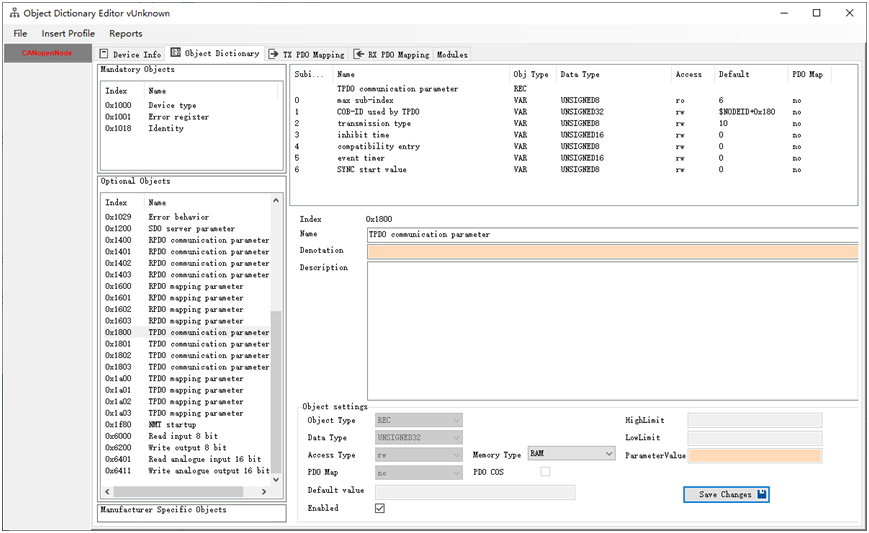
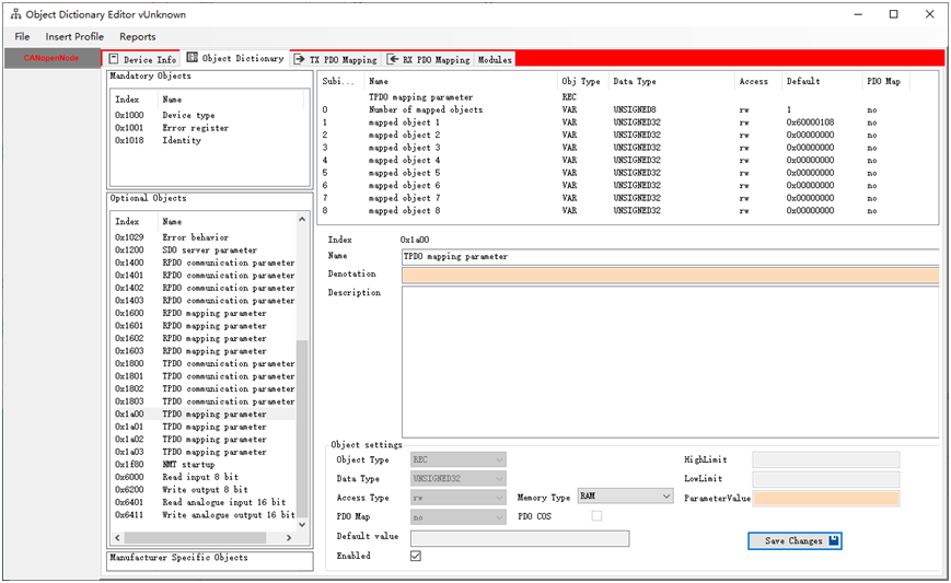
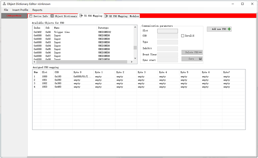
CANOpen设备的配置情况,0x6000开始保存8字节的开关量输入信息,TPDO[1]配置为同步循环发送,同步10次发送1次。TPDO[1]中就包含一个数据字节,为0x6000对应的第一字节的开关量。具体配置信息见下图。 设备地址设置为10.
设备启动时: 如下图所示,首先发送0x70A 1 0x00 表示设备上线,然后循环发送0x70A 1 0x7F 表示CANOpen设备进入到预操作状态,等待CANOpen主机的进一步操作。

主机启动:
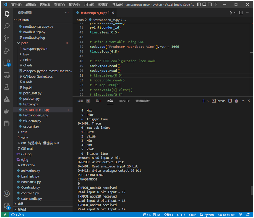
主机输出log信息 PS D:\MyProg\python> & "C:/Program Files/Python38/python.exe" d:/MyProg/python/pcan/testcanopen_m.py 0x1000: Device type 省略部分信息 0x100A: Manufacturer software version 0x1018: Identity 0: max sub-index 1: Vendor-ID 2: Product code 3: Revision number 4: Serial number 0x1800: TPDO communication parameter 0: max sub-index 1: COB-ID used by TPDO 2: transmission type 3: inhibit time 4: compatibility entry 5: event timer 6: SYNC start value 0x1801: TPDO communication parameter 0: max sub-index 1: COB-ID used by TPDO 2: transmission type 3: inhibit time 4: compatibility entry 5: event timer 6: SYNC start value 省略部分信息 0x6000: Read input 8 bit 省略部分信息 PRE-OPERATIONAL(当前设备状态) CANopenNode(Manufacturer device name) 0 (Vendor id) (主机读取TPDO和RPDO配置信息) (以下为设备转如操作状态,同时主机提供同步信号) TxPDO1_node10 received Read input 8 bit.Input = 17 TxPDO1_node10 received Read input 8 bit.Input = 18 TxPDO1_node10 received Read input 8 bit.Input = 19 主机控制设备进入预操作状态,并读取厂商信息和id
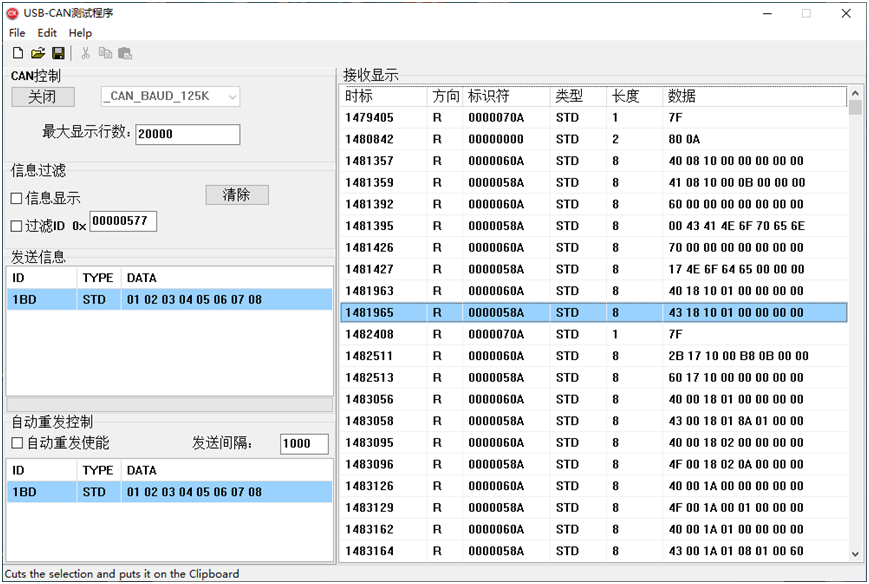
主机读取TPDO和RPDO配置信息 主机启动设备进入操作模式,并且提供同步信号。 主机操作设备进入操作状态,0x000 2 0x01 0x0A 设备进入操作状态: 0x70A 1 0x05 主机启动同步信息 0x080 ,同步信号间隔0.1秒 在同步信号的作用下,从机间隔10个同步信号,发送给意思TPDO[1]信息。TPDO[1] 配置为同步10次,循环发送。从发送的CAN总线监视设备上可以清晰的观察到间隔10个ID = 0x080的同步帧后,设备发送了一个ID = 0x18A的TPDO[1]数据帧。数据帧中包含1个字节的开关量输入数据,这个数据认为处理为每秒加1,所以我们可以看到ID=0x18A的数据在逐次递增。 到此,执行CANOPEN协议的设备已经正确的运行起来了。
| 


 发表于 2023-2-3 14:42:48

 发表于 2023-3-14 11:06:21